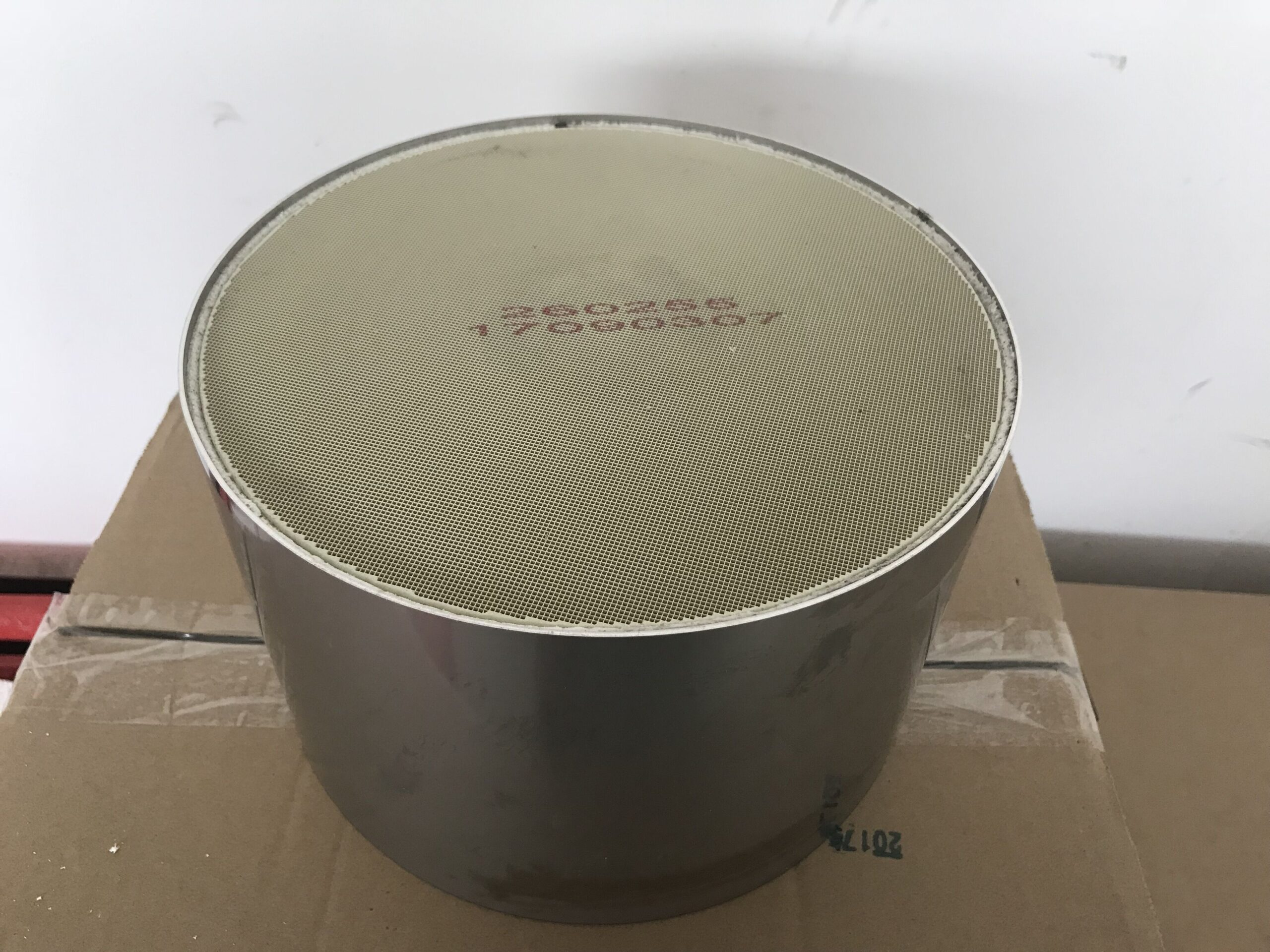
An engineer designing an aftertreatment SCR assembly starts with a set of engine measurements, not a catalyst name. Exhaust flow, temperature, NO and NO₂ fractions, expected NOx output, available packaging space, and the allowable pressure loss define the task. The active chemistry and the honeycomb carrying it must both fit those conditions.
Vanadium pentoxide technology supplies an active-material option within a diesel SCR assembly whose dosing and physical layout still require engineering. Urea dosing, mixing distance, inlet uniformity, operating temperature, and substrate geometry determine whether the intended reaction can occur throughout the unit. The design sequence therefore moves from measured exhaust conditions to chemistry and then to physical integration.
Define the Reaction Environment
The temperature distribution matters more than a single rated point. An engine may spend long periods at modest load, then reach substantially hotter exhaust during acceleration or sustained work. A candidate washcoat has to be assessed against the time spent in each range and the NOx mass entering during those periods. Peak temperature alone gives an incomplete picture.
Ammonia formed from the injected urea reacts with nitrogen oxides over the SCR surface. The proportion of NO to NO₂ can shift the available standard and fast SCR pathways, so an inlet NOx number without composition is not a full reaction specification. Dosing must also account for the risk of excess ammonia at conditions where conversion slows.
The upstream layout can change the chemistry seen by the SCR inlet. Oxidation equipment, piping, and dosing hardware affect temperature, NO/NO₂ balance, and reductant distribution. An aftertreatment SCR design therefore needs inlet measurements at the proposed catalyst position. Values measured only at the engine outlet may miss changes introduced before the exhaust reaches the active surface.
Hualian Catalyst lists an approximate temperature window of 230–470°C for its vanadium-based metal oxide diesel SCR washcoat. Its boundaries screen candidate engine conditions; conversion can vary inside them. The planned reductant rate, space velocity, inlet composition, and conditioned component state determine test points establishing the response of that proposed washcoat.
Translate Chemistry into Honeycomb Geometry
The inlet transition sets the flow pattern presented to the honeycomb face before individual channels divide the stream through the catalyst. Channel density, length, frontal area, and coating loading influence the contact opportunity and pressure drop. More nominal surface area is useful only if exhaust and reductant reach it evenly; a poorly distributed stream can leave part of an otherwise suitable element underused.
Hualian’s diesel SCR products are described in square and cylindrical honeycomb formats, with multiple cells-per-square-inch (CPSI) choices and customer-specific dimensions. A round canister and a rectangular installation envelope impose different sealing and mounting problems. The geometry choice belongs in the system drawing alongside flow direction, connector position, sensor locations, and service access.
Vanadium pentoxide is often discussed as if the active material by itself determines the converter size. In practice, the design must accommodate a required reaction rate at the available temperature while staying within a pressure budget. Increasing length can add contact time, yet it also changes backpressure and thermal mass. A larger face may relieve velocity but require more space.
Uniform reductant mixing is a separate geometric question. The injection position and distance to the honeycomb affect whether droplets evaporate and whether ammonia reaches the full face. If local zones receive too little reductant, catalyst capacity elsewhere cannot compensate automatically. If other zones receive too much, ammonia slip or deposits may become a system concern.
Check Thermal and Mechanical Interfaces
The support must survive repeated changes in exhaust temperature and mechanical loading. Hualian describes its honeycomb as having high surface area with low pressure loss, together with resistance to thermal expansion, heat shock, and vibration. These characteristics matter at installation because a cracked or displaced substrate changes the actual flow path and contact area.
Expansion loads reach the substrate through its housing and retention system, while brackets and exhaust piping transmit engine and vehicle vibration. A mounting design that restrains thermal movement can impose stress even during satisfactory gas conversion. Package durability is therefore assessed through those load paths and connections; steady-flow activity on a laboratory sample answers a separate reaction question.
The design file also separates substrate strength from assembly evidence. Welds, seals, and brackets introduce their own failure points. The complete unit must withstand both the thermal and vibration cycles expected in service.
Pressure measurements should cover the operating range rather than a nominal flow alone. Backpressure rises as mass flow increases, and additional elements in the exhaust line contribute to the total. The acceptable value is set at the engine-system level. A low-pressure-loss substrate still needs confirmation after the selected cell density, dimensions, coating, and housing are assembled.
Before sign-off, measurements from one assembled configuration must cover NOx conversion, ammonia behavior, pressure loss, temperature profile, and structural integrity.
The selected vanadium-based formulation needs an inlet condition it can use, while the chosen honeycomb and housing must keep that condition available over time. The approved aftertreatment SCR design identifies the washcoat, honeycomb, housing, and dosing layout tested on the measured engine duty.
