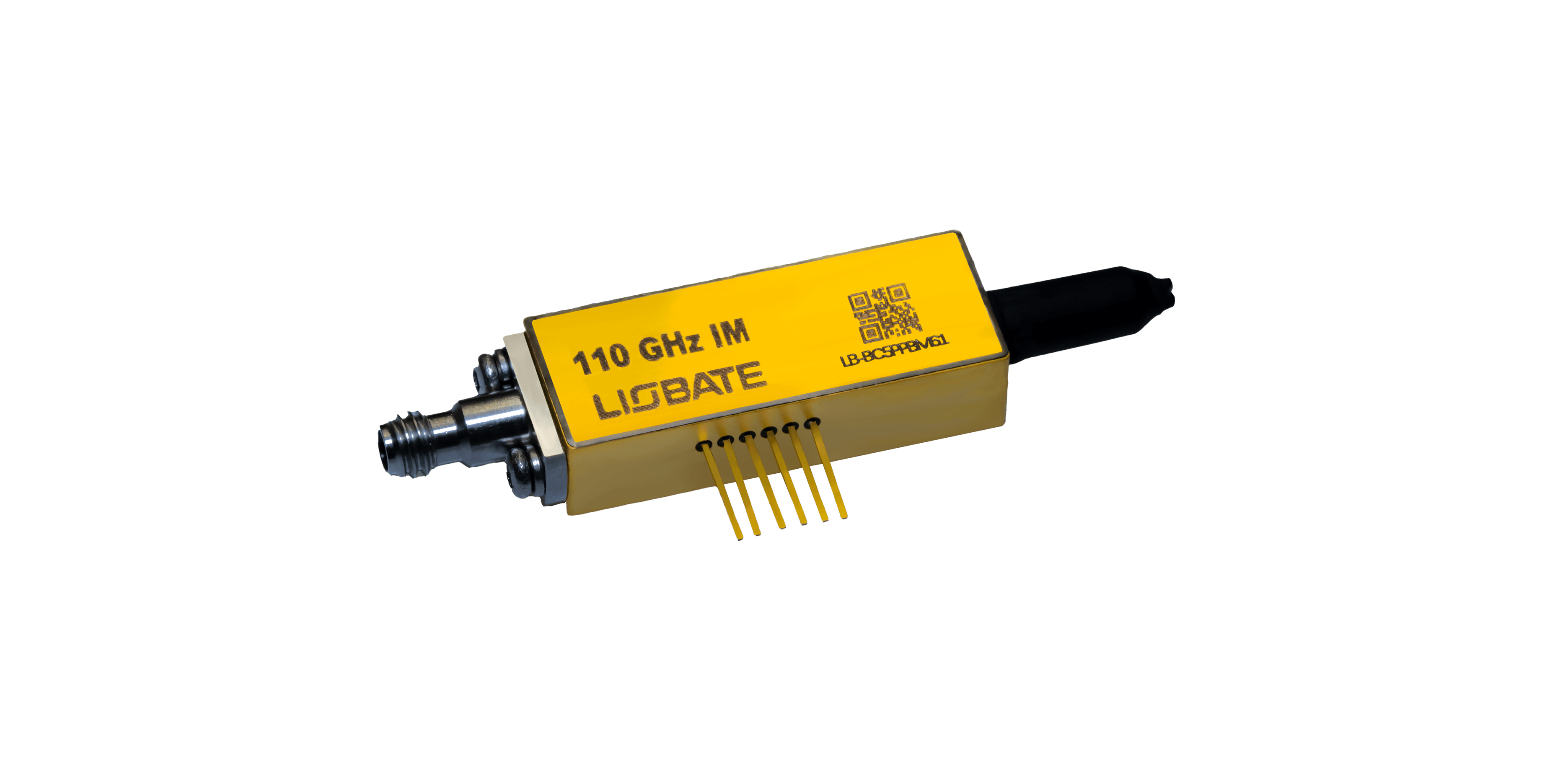
Light carries information efficiently, but it still needs a controlled method for receiving an electrical data signal. When they design a modern optical system, the intensity modulator often performs that conversion by changing optical power in step with an applied voltage.
Its role may appear simple, yet the quality of that conversion affects the entire link. They use intensity modulation in several contexts: short data-center connections, telecom transmitters, laboratory signal generation, OEO conversion, and system validation.
Each environment places different limits on bandwidth, optical loss, linearity, bias control, and packaging. A useful device must therefore be specified in a way that allows engineers to connect component data with the planned operating conditions.
Modern photonic applications increasingly require faster waveforms, lower electrical power, and compact multichannel layouts. An electro-optic intensity modulator can address those needs when the electro-optic material, waveguide geometry, electrodes, and package are designed as one signal path rather than as independent technical elements.
Controlling Optical Power for Data and Measurement
In a typical interferometric design, the incoming light is divided between two waveguide arms. An electrical field changes the optical phase in one or both paths, and recombination converts that phase difference into an output-power change.
They value this mechanism because the transfer curve can be biased for digital transmission, analog operation, or measurement tasks. Liobate associates its TFLN devices with high bandwidth and low insertion loss. Within photonic applications, these characteristics can preserve fast electrical content while limiting the optical power consumed by the modulator.
The result is useful when connectors, fiber coupling, electrode transitions, and driver matching maintain the same performance after packaging. An electro optic intensity modulator also needs stable bias.
Temperature, optical power, and material or packaging effects can move the operating point, changing extinction ratio and waveform symmetry. They include bias-control requirements in the architecture review so that monitoring circuits, calibration routines, and service procedures are planned before the product reaches final qualification.
Adapting One Function to Different System Architectures
Data-center links typically emphasize compact size, high lane rate, and low energy per bit. Telecom systems may add greater reach, wavelength management, and stronger environmental requirements. Test equipment can prioritize linearity, repeatability, and connector flexibility.
The same modulation principle can serve each market, but the acceptable package and control strategy are not identical. The company reports that its intensity-modulator chips can support 400G and 800G communication equipment, while 67 GHz-plus devices can be used for OEO conversion and validation.
These photonic applications show why bandwidth should be paired with context: a device used to transmit traffic may be optimized differently from one used to create a calibrated test signal. For coherent or complex transmitters, an electro-optic intensity modulator may also be combined with phase-control functions or arranged in nested interferometers.
They assess channel balance, electrical skew, optical phase error, and integration density in such cases. These parameters often influence final error performance more strongly than a single upper-bandwidth figure. Sensing systems add another variation.
They may use controlled optical power for ranging, calibration, or interference measurements rather than data traffic. They examine noise, waveform fidelity, optical power handling, and timing stability in those cases, showing why the same modulation function can require a very different acceptance specification.
Evaluating Performance Before Production Integration
The evaluation starts with parameters including wavelength, data rate, modulation depth, optical input power and required extinction ratio. Subsequent assessments cover insertion loss, half-wave voltage, frequency response, impedance, return loss, packaging interface and operating environmental range.
This sequence prevents the team from selecting a device that looks fast but conflicts with the available driver or link budget. Production qualification must also show consistency. An electro-optic intensity modulator should be sampled across lots, temperatures, and repeated connection cycles where relevant.
Photonic applications intended for commercial systems need clear acceptance limits and traceability, because small changes in electrode or coupling performance can create larger variation at the module level. Liobate can provide TFLN chips and packaged devices for this evaluation, but they would still verify every material parameter in the customer configuration.
A test report should explain measurement setup, calibration, optical reference planes, electrical drive conditions, and whether quoted loss includes coupling. That detail makes comparisons fair and reduces integration surprises. From a sourcing perspective, the right component can lower risk beyond its purchase price.
Reduced drive voltage may ease driver design, lower optical loss may protect receiver margin, and broader bandwidth may extend the same platform into a later product generation. They convert each technical benefit into a documented system impact before approving a design.
They also avoid forcing one device into every program. A laboratory instrument may accept a larger package for connector access, while a transceiver needs dense integration and production-friendly assembly. Matching form factor, control method, and qualification depth to the intended use keeps the design practical and prevents unnecessary complexity.
The practical value of an intensity modulator appears in the transmitter around it. A comparison that includes Liobate therefore needs to account for RF matching, bias control, loss, package behavior, and the workload placed on production test.
